.png)
Engineering Portfolio
by Pablo Villa
I have developed a well-rounded, multi-disciplinary engineering background with a strong foundation in engineering design, structures, thermodynamics, and controls in my 4 years at Purdue University studying Aerospace Engineering. I bring significant demonstrated experience with designing, building, and flying unmanned aerial vehicles (UAVs) under 55lbs as well as utilizing camera & gimbal systems ranging from tiny GoPros to movie-grade cinema cameras, among many other skills I have picked up on through personal interests, research, and an internal motivation to get up every day and do something to help me become a great engineer.
Most recently as an undergraduate research assistant, I have been in charge of creating and testing the camera system for Purdue's zero-gravity cryogenic bubbles phenomena experiment, dubbed "Cryobubbles" by the team, under the guidance of Professor Steven Collicott. My camera system involves mirrors to capture visual data in tight spaces as well as a power system and HDMI multi-view interface to monitor all cameras in-flight, and has been redesigned from the previous system to successfully capture data in a significantly greater resolution and with monitoring capabilities that were previously unreliable. The experiment is currently set to fly on G-Force One out of Fort Lauderdale on April 22nd and April 23rd, 2024, and will be paramount in providing invaluable data for countless future space missions across the globe that could benefit from vent-less cryogenic storage systems.
STOL, High Cruise Speed Jet

Car-mounted test stand for various airfoils & wings to verify XFLR5 results and choose a final wing from data. Attaches to car via 15mm rails and large suction cups.

Variable exit diameter nozzle for a 90mm electric ducted fan. Expected top speed of over 100m/s, or 223mph with chosen engine. The red spinning ring inside of the dark grey cover, shown hidden above, spins 10 ball joint arms in unison, each attached to the 10 controlled flaps with 10 sealing flaps following suit with the use of rails and miniature springs. The ring essentially rotates on a large ball bearing consisting of over 80 2mm steel balls embedded into the main 3D printed chamber.


Pictured above (left) is a rough CAD rendering of the overall aircraft design. The inspiration for my design was mainly the Northrop YF-23, as I was interested in creating a mock supersonic aircraft, and the YF-23 had very promising flight characteristics and performance despite the Lockheed YF-22 beating it for the contract they were battling for in 1986.
I was also very interested in the large, all-moving V-tails which allowed the aircraft to be highly maneuverable, and is thus a significant part of my design derived directly from the YF-23. The large wing area is a significant part of what will allow this aircraft to land slowly, one of my main performance goals.


My results so far suggest that XFLR5 actually severely underestimated the performance of this airfoil and wing configuration with flaps and slats, although it aligns closer with the clean configuration. This makes sense, as XFLR5 seems to struggle a lot more with accuracy once slats are involved. Additionally, my results have helped me determine that the added weight and complexity of slats will likely not lead to a sufficient increase in lift to justify it, at least with this iteration of my aircraft.
Shown above on the left is the car mounted test stand and camera I created. The vertical slot that the wings have to move along was placed so that the wing could move around a range of XFLR5 predicted center of pressures for the configurations I chose to test, to reduce the amount of friction it must overcome to lift up along its slot. The video shown has an overlaid video of my car's spedometer synced with the camera's view of the aircraft. String was placed along the wing to determine flow type and potential stalls. In the video, the wing lifts around 18mph, but later falls when the car begins to slow down around 16mph, so I interpolated those values to take 17mph for the speed at which this wingat the given mass created the necessary lift to overcome gravity, and derived a lift coefficient from those values. I did this about 18 times to determine experimental plots, shown above in comparison to respective XFLR5 results.
THE 'NOVOA', ELECTRIC STOL JET, MAX. SPEED UP TO 220mph
To pursue my personal engineering endeavors while working full-time, I have been designing a 1 meter wingspan electric jet aircraft during my free time at home. It has taken hundreds hours to date since beginning the project in Summer 2024. No part of it existed before I started designing it, so I wanted to be very careful about my airfoil choice and conducting proper XFLR5 analyses as well as real life testing before manufacturing the complex design (although I have already created and manufactured the variable nozzle shown above, as I expected it to be one of the most difficult parts to create). I am naming it the Novoa, after my grandfather's second last name, who sparked my passion for aircraft when I was very young.
MANUFACTURING and DESIGN
Typical manufacturing methods with remote control aircraft involve sanding down the leading edge by hand, which can lead to inaccurate airfoil behavior and characteristics since the shape of the leading edge is a crucial aspect to the behavior of a given airfoil. However, since I am 3D printing the majority of the components, and with the use of Bambu Lab's Aero (Foaming) PLA material, I can not only reduce the weight of the wings by 50% compared to when using typical PLA materials, but can achieve a perfectly shaped airfoil by printing the wing in pieces, vertically oriented on the printer bed. The side profile will therefore be extremely precise. During final touches later down the road, I will first sand down the assembled wings to get rid of any major ridges due to the 3D print layer lines, then apply a few coats of Tamiya spray filler/primer, sand with various levels of grits again to achieve a very smooth surface, and finally apply the necessary amount of airbrushed coats of glossy white for a beautiful finish.
Given my chosen manufacturing method, I can create a very accurate wing compared to XFLR5 analyses that I have been conducting, and therefore wanted to produce a test stand to test these airfoil's behaviors in real life in comparison to their respective XFLR5 results to select a final airfoil and wing before designing the final aircraft to manufacture. Since I want to create an aircraft with a smooth, blended body, creating the wing before anything else is crucial with the use of Fusion360, because I am using parametric modeling methods and need the location of the wing's surfaces to create a blended fuselage.
CUSTOM TEST STAND
I wanted to use a test stand that I could mount on top of my car since I do not have access to a wind tunnel, and wanted it to be modular so that I can test any airfoils I'd like with the same stand. I am placing short strings along the top surface of the test wings to be able to have a rough visual of when a stall may begin to occur by increasing the angle of attack (AoA) and visualize when and where turbulence occurs. The stand is adjustable by 2.5º AoA with my current design. By driving the car in empty flat land, and setting up a camera on top of my car, I can audibly call out the current speed of the car to be heard on the camera's audio by connecting a microphone to the camera's audio input, which I will place inside the car for clear audio. With each iteration for a given wing configuration, I will set the wing at a given AoA and then drive my car in a straight line from 0-40mph to collect data on the speed at which the wing creates enough lift to lift the total weight of the wing, which I have added weight to forward of the neutral point. The wing is free to move about a half-inch in its vertical axis (which is angled with respect to the set AoA). Therefore, when the necessary airspeed is achieved at a given AoA, the wing will visually lift upward within its vertical slot I created into the test stand. I will take note of the current wind speed and direction with every iteration, and do my best to drive straight into the wind to be able to easily add that wind speed to the car's reported ground speed, and then assume those values as the airspeed of the test wings to derive necessary variables from the data.
ADJUSTABLE HIGH-LIFT SURFACES & PERFORMANCE GOALS
Additionally, my scaled-down test wings have adjustable leading and trailing edge flaps in order to be able to test different configurations and determine what the optimal takeoff and landing speed can be with every airfoil I test. This will also help determine whether adding the complexity and weight of a leading edge flap will be worth it or not. My performance goal for this aircraft is to be able to have a short takeoff/ landing distance (STOL) while also being able to transition into a high-speed cruise configuration and be highly efficient at higher speeds. My electric ducted fan of choice is Schubeler's 90mm DS-51-AXI HDS / HET 1125kV engine, as it can produce up to 55 Newtons of thrust at its highest rated voltage of 44.4V using a 12 cell Lithium Polymer battery. This will allow for a maximum thrust-to-weight ratio close to 1.5 if I keep the weight of my aircraft at 3.5kg or less, which will be more than plenty for my purposes as I aim to achieve an aircraft with realistic flight characteristics. However, reaching a net weight closer to 3kg will also help me keep the take-off and landing speed lower. The airspeed goal with high-lift devices at takeoff and landing is 25mph, and am currently undergoing testing with different airfoils on my car-mounted test stand to determine a coefficient of lift using the data I am collecting to see if this will be possible. A 30mph speed will be acceptable, but is a relatively high speed to land at with remote control aircraft.
UNDERGRADUATE RESEARCH
Cryobubbles | Cryogenic Bubble Formation Phenomena Experiment - Building on NASA's ZBOT Observations
Purdue's 'Cryobubbles' experiment was created to understand an unexpected bubble formation phenomenon during a tank-pressure control strategy test of NASA’s Zero Boil-off Tank (ZBOT) on the International Space Station. Thanks to their grant, our experiment has been designed by undergraduate students to test hypotheses on a parabolic flight as to the cause of the phenomenon.
Overall Experiment


Front view of LN2 test chamber with polyisocyanurate insulation

One of 8 test vessels, made of acrylic. Screen can be seen inside


Test vessels and interior plumbing of LN2 test chamber
Window Stack-up


Our initial window stack-up for testing thermal fracture is installed, with O-rings inside seats machined into flanges.

The first and second window flanges can be seen to be frosted during a thermal fracture test I helped perform.

The recent implementation of gaskets as opposed to O-rings, which caused failure, is seen above before actual installation.

A recent "soapy water" test was conducted to check for leaks with the new addition of gaskets.
Camera System

Mirror and camera hardware (left and right respectively) are shown for the most complex placement of the 4 cameras due to a tight space.

Mirror being used to view the 2 vessels from a longer distance creating a more linear image with a longer 10mm lens rather than a wider 4.5mm lens, which was impossible to install due to space restrictions.

The GoPro's view through the mirror placed at a 45 degree angle to the camera's line of view.
Custom Solar UAV | 2.1 Meter Wingspan, 4 Engines
This solar UAV project was developed over the summer of 2023 for a research study at Purdue University under Professor Richard Voyles. This research was focused on analyzing the effects of attaching solar cells in various configurations on the top and bottom surfaces of a UAV to improve the aircraft's efficiency and performance.
The scope of my research responsibilities was to develop the platform and ensure all systems and items were working through testing.
Development included: parts selection, design , fabrication, assembly, tuning and autonomous flight calibration. I tested the solar power system on its own and the UAV platform on its own. The full system test will be conducted by PhD students based on the solar UAV study hypothesis from the original paper.
One of the biggest challenges was being able to carefully solder and attach the delicate solar panels to the wing, which previous students were unsuccessful with but myself and a graduate assistant were able to successfully install the solar panels on the wing and measure their voltage across both wings connected.
Overall CAD


Full Wing With Solar Cells Installed

2D Layout for Laser Cutting Foam

Engine Cells


Pictured above is one of four engine cells with a mounted motor and propeller as well as electronics installed inside. Vents were added to allow for passive cooling during flight to prevent system failures.


Pictured above is the right foam wing assembled and with the 3D-printed ribs and carbon fiber spars. The wing is wired wing a custom connector for quick attachment in the field without fiddling with 6 different PWM cables.
Flight Testing

Conducted successful flight tests with a maximum continuous flight time of almost 1 hour. All flight data was recorded on the UAV and on the ground station via wireless data telemetry. Flights were conducted using waypoint GPS navigation and onboard fly-by-wire technology which I programmed using Q-Ground Control Software.
Shown on the right is a video of my research partner, Chin, helping us release the aircraft with a running start in order to avoid the need for landing gear which added weight and complexity to the aircraft, and was not necessary for the scope of the project.
I can be seen in the blue and white shirt controlling the aircraft, in the process of taking it up to a good cruising altitude to perform autonomous mode testing.
PERSONAL PROJECTS
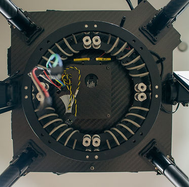
X8 Heavy-Lift Octo-copter | 8 Engines, Coaxial Formation
This is another work in progress project that I have been developing since roughly my junior year of high school. The ultimate purpose is being able to lift a heavy and high-value cinema camera & gimbal payloads for the use of aerial footage for video projects. This required cohesive programming, redundancy, and powerful energy distribution methods.
Admittedly, this is my worst project in terms of proper documentation, and spans many years. Many of the original pictures I took during manufacturing were lost with a damaged hard drive in 2019, or sit on an almost unusable computer in my Connecticut hometown of New Canaan. Much like my Nova H210 UAV, it is currently sitting in my parents' basement waiting to be improved on when I get the chance to go home again, as I don't get to go home often. The pictures below were taken in that basement.


Electronics Stack-up

Side view of all electronics in the drone. Bottom layer (at the level of the arms) contains electronic speed controllers, solid copper power distribution board (PDB) and associated power and signal cabling. The thicker layer above it contains the flight controller, receiver, signal transducer, and associated cabling. At the top the two 6-cell LiPo batteries can be seen.


Original 2017 Notebook Sketch / Design

Nova H-210 | 12-ft Wingspan, Tri-fuselage RC Aircraft
This was a passion project that I began back in my sophomore year of high school as an independent study, and have been working on it ever since. It features a triple fuselage and long wing design based on the Rutan Voyager, but I meant to create more of a "reconaissance" type aircraft that could cruise at low speeds and be as realistic as possible in terms of capabilities, such as retractable landing gear, differential thrust, flaps, and steerable front gear for taxiing.
My remote-control aircraft hobby has always been driven by an inexplicable desire to take off, fly, and land like a real aircraft and with as much accuracy as possible, including advanced flight concepts like crabbing into cross-winds for landing. One of my ultimate goals with my custom RC aircraft is to one day expand on this design or create a completely new one to create a first-person-view aircraft with a cockpit camera that can rotate with the movements of my headset through which I will view the flight, and do so in the beautiful deserts of the west.

FIRST DESIGN: Pictured is a sketch I created of this aircraft inspired by the RM76 Voyager (pictured on right) in November 2016. I did not begin to create the real model until roughly 2018.

INSPIRATION: Rutan Model 76 Voyager: First aircraft to fly around the world without stopping or refueling, piloted by Dick Rutan and Jeana Yeage.


Pictured above is myself standing next to my near-completed aircraft, during an initial test on my high school track (left) and on the workbench a week or so earlier (right).
Middle fuselage

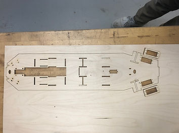
Pictured left is my laser-cut baseplate designed in CorelDraw X7 for the middle fuselage, and on the right is the fuselage once I had the majority of the wiring set up and organized. The carbon fiber support system to help strengthen the fuselage against torquing, which was not part of the original design, is seen on the bottom. Wiring from the wings and "fuel" fuselages was brought through the carbon fiber tubes to the main fuselage to avoid moving wires through the delicate wings.

Pictured above is the back of the left and right fuselages holding the left and right retracts.
Wing Box


Middle Wing Structure


Wings and Wingtips


Lessons Learned


Sizing of all aspects of an aircraft is crucial, which I did not fully know as a high school sophomore when I began the project.
Consideration of all internal forces that could act on an airplane, from its own weight and structure, is extremely important.
Adding motors for fun or for "more thrust" without justification can cripple the performance of the aircraft.
Careful placement of landing gear, rather than only considering if it will tip over or not, should be done. In my design, I should have placed it closer to the the trailing edges as it would experience a lesser moment and impact upon landing.
Future Personal Project | VTOL Craft
